Mountaintech 38" +3" A Arm Kit |
Mountaintech 43" +2" Trail A Arm Kit |
Mountaintech 41" +2" Crossover A Arm Kit |
FX Nytro Running Board Kit (Late Version) |
FX Nytro Running Board Kit (Early Version) |
PZ Phazer Running Board Kit |
Mountaintech FX Nytro Skid Plate |
Mountaintech FX Nytro Shorty Skid Plate |
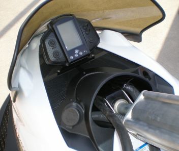
Mountaintech Instrument Panel Vent |
Mountaintech IP Vent with IP Gauge Mount |
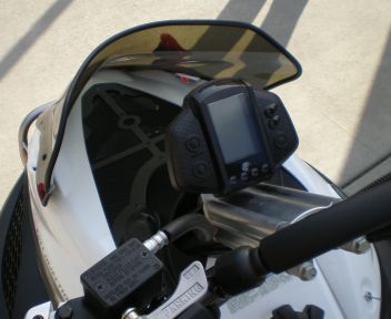
Mountaintech IP Vent with Steering Post Gauge Mount |
Mountaintech Black or Silver Steering Post Gauge Mount
Canadian and International Orders, please inquire about shipping charges before ordering

|
|
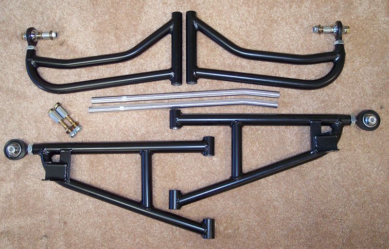
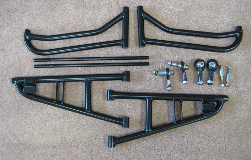
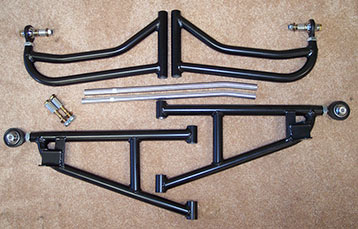
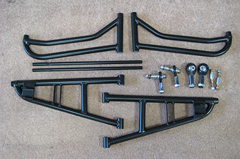
Mountaintech 38" +3" A Arm Kit
After a full season of extensive testing Mountaintech is releasing the +3" Kit for the FX Nytro.
Key design features
- +3" forward
- 38" ski stance
- Proper shock placement
- Adjustable camber
- Independently adjustable caster (21-27 degrees, an industry first)
- No shock mods required
- Use of stock spindle
- Rugged tie rods
- High misalignment rod ends (3/4" bottom,5/8" top)
3" forward is the optimal dimension. Going further forward does not improve overall performance, it just creates more challenges in regards to shock angles, tie rods, and high centering of the sled when loading and unloading into pickup trucks and sled decks.
38" ski stance provides both trail stability and off trail maneuverability. Remember, pushing the spindles forward makes the sled perform as if it has a narrower ski stance in many situations.
Being able to adjust caster is important for off trail performance. This feature allows you to set the caster at the sweet spot (23-24 degrees).
There is no need to replace the stock spindle. Placing a spacer between the upper A arm and spindle modifies the camber gain when the suspension compresses.
When it comes to tie rods for a +3" kit, the best solution is a pre bent OEM tie rod. They are very strong, and when bent in the correct place, are virtually bulletproof.
Mountaintech A Arms accept OEM and aftermarket style bushings. (bushings not included)
*08/09 models require upper A arm inner tube P/N 8HK-23373-00 QTY 2
** Kit must be used with "8GL" spindles (found on all 08 Nytros,09 MTXs and 2010 base model MTXs) **
*Price:
$769 - plus
shipping
|
| Mountaintech FX Nytro 38" +3" A Arm Kit Installation Instructions |
Click to show instructions
**2008-2009 Nytros require updated collars for upper A arms P/N 8HK-23373-00 QTY 2
** Mountaintech A arms have no provision for mounting a sway bar. Sway bar must be removed if one exists.
- Remove hood, upper and lower body side panels, front bumper, and nose panel.
- Raise the front of the snowmobile so skis are off the ground using a suitable lifting device.
- Remove shock absorber. Put aside the hardware used to fasten the shock to the lower A arm. It will be reused. Remove pushpin fasteners that hold on the plastic at the A arms.
- Remove the spindle/ski assembly from the upper and lower A arm and tie rod end. Put aside the hardware used to fasten the spindle to the lower A arm, and the hardware used to fasten the spindle to the tie rod end. They will be reused.
- Remove the upper A arm by removing the fastening bolt. Remove the lower A arm by removing the forward and rear bolts and nuts. The rear nut is difficult to access. Take your time. A telescopic magnet and patience helps. Remove the aluminum collars from the A arms.
- Remove the OEM tie rod by loosening the inner jam nut and rotating the tie rod CCW to unthread it from the inner tie rod end. Install the new prebent tie rod with the end closest to the bend facing inwards. A telescopic magnet holding the inner tie rod shaft helps to get things started. Apply some blue thread locker to the tie rod inner threads and thread it onto the inner tie rod. There should be about 6 threads showing on the inner tie rod once the jam nut is tight. Apply blue thread locker and tighten jam nut securely. The bend in the tie rod must face towards the rear of the snowmobile and the tie rod should have an equal amount of up and down travel as the inner tie rod end rotates on it's ball stud. If not, loosen jam nut and readjust.
- Install bushings in Mountaintech A arms.
- Install aluminum collars previously removed from stock A arms into Mountaintech A arms.
- Install Mountaintech lower A arm using blue thread locker on the threads of the OEM fasteners. Torque bolts to 32 ft/lbs. Reposition the body plastic that sits behind the upper A arm, and reinstall the pins. Install Mountaintech upper A arm using OEM bolt. Apply blue thread locker to the bolt threads and torque bolt to 32 ft/lbs.
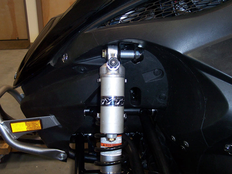
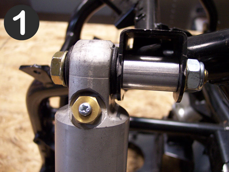
- Install shock absorber to subframe (top mount) as shown in Pic #1 with supplied hardware. Apply blue thread locker to bolt threads and torque bolt to 47 ft/lbs. Install bottom of shock absorber to lower A arm with the OEM hardware (bolt, nut, 2 thin spacer washers). Apply blue thread locker to bolt threads and torque bolt to 32 ft/lbs.
- Thread lower A arm rod end with jam nut into lower A arm until about 10 threads are left showing. Thread upper A arm rod end with jam nut into upper A arm until about 5 threads are left showing. Use antiseize lubricant on rod end threads when installing into A arms.
- Reinstall spindle/ski assembly using OEM nut and bolt to secure it to the lower A arm rod end. Do not tighten nut and bolt at this time.
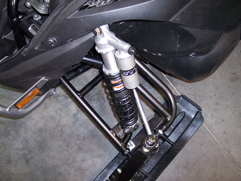
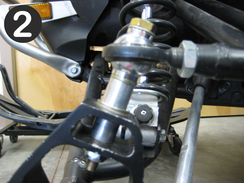
- Attach upper A arm rod end assembly to top of spindle with supplied hardware as shown in Pic #2. Tighten nut and bolt but do not apply blue thread locker at this time.
- Lower snowmobile to the ground. Push down on the nose of the snowmobile several times to settle the front suspension. Put a long straight edge along the edge of the track extending forward along side the ski. With handlebars dead center, align ski to the straight edge so it is toed out about 1/4". Loosen outer tie rod end jam nut and adjust the outer tie rod end so it will slip into the spindle. Secure with the OEM hardware. Apply blue thread locker to the threads of the bolt and torque to 20 ft/lbs.
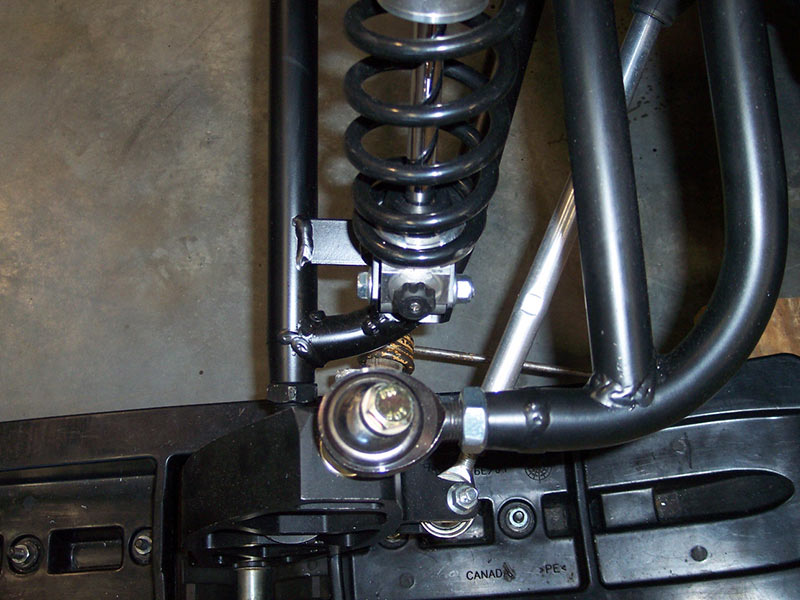
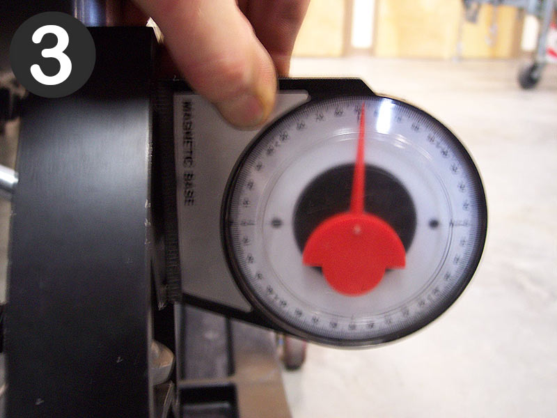
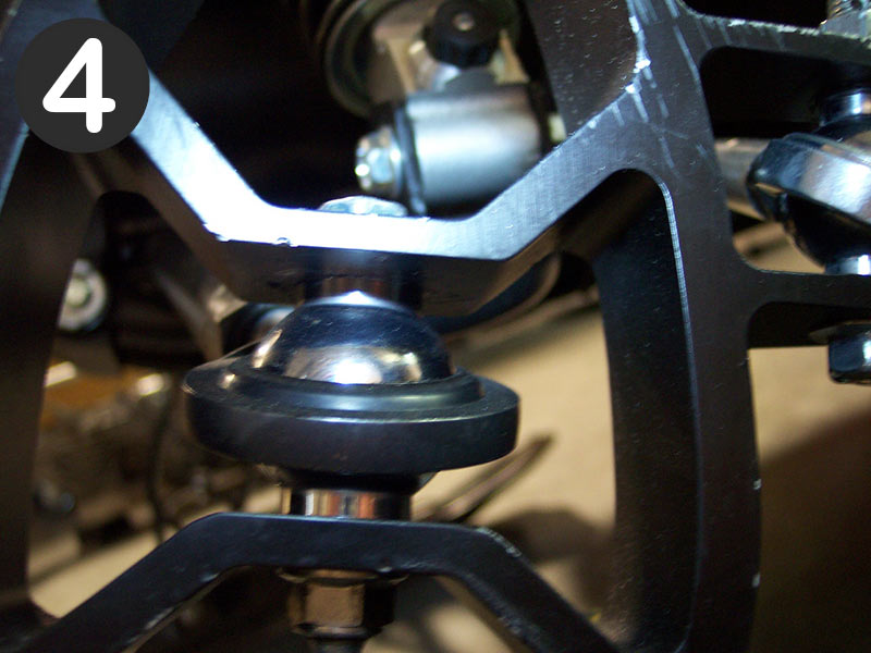
- Check camber by putting an angle gauge against the spindle. It should be between 1 and 2 degrees negative. See Pic #3. Negative camber means the top of the spindle is closer to the snowmobile than the bottom of the spindle. If not, adjust lower A arm rod end in or out to achieve this value. Apply blue thread locker to threads of bolt that attach lower A arm rod end to spindle and torque bolt to 47 ft/lbs. Apply blue thread locker to the threads of the lower A arm rod end and tighten jam nut securely. Make sure when you tighten the jam nut that the black body of the lower A arm rod end is parallel to the spindle mounts, so the rod end does not contact the spindle through out the spindles movements. See Pic #4.
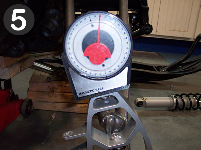
- Check caster by putting an angle gauge on the top flat surface of the spindle. See Pic #5 It should be 23-24 degrees. If not, adjust upper A arm rod end in or out to achieve this value. Apply blue thread locker to the threads of the bolt that attach the upper A arm rod end assembly to the spindle and torque to 47 ft/lbs. Apply blue thread locker to threads of upper A arm rod end and tighten jam nut securely.
- Re check ski alignment to make sure it hasn't changed. Adjust if necessary.
|
 |
|
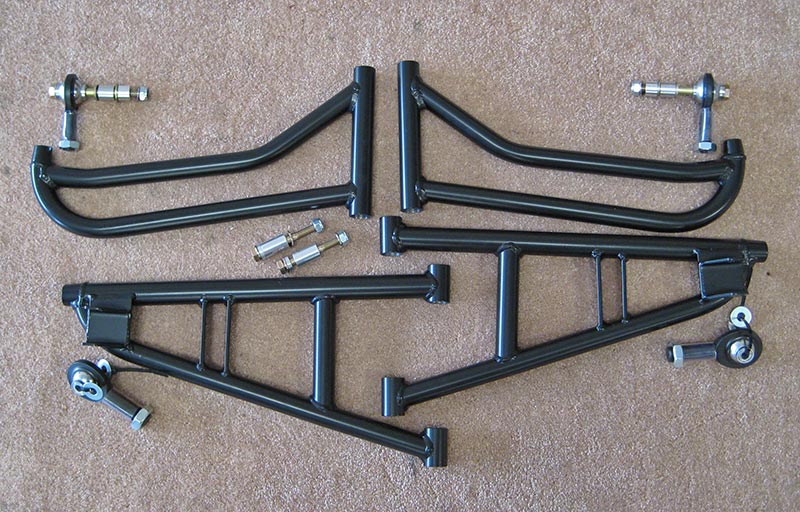
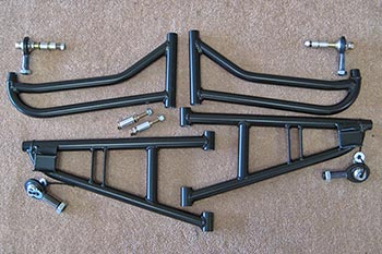
Mountaintech 43" +2" Trail A Arm Kit
Simply the best trail A arm kit available for the FX Nytro. At 43" wide and 2" forward, this front end turns the Nytro into a whole new animal. It is also the only kit on the market with fully, and independently adjustable caster and camber.
Key design features
- 43" ski stance
- +2" forward
- Proper shock placement
- Adjustable camber
- Independently adjustable caster (about 21-27 degrees, an industry first)
- No shock mods required
- Use of stock spindle
- High misalignment chromoly rod ends (3/4" bottom, 5/8" to
2008 models require upper A arm inner tube P/N 8HK-23373-00 Qty 2
*Price:
$799 - plus
shipping
|
| Mountaintech FX Nytro 43" +2" A Arm Kit Installation Instructions |
Click to show instructions
**2008 Nytros require updated collars for upper A arms P/N 8HK-23373-00 QTY 2
**2010 and up Nytros require shim washers between lower A arm rod end and spindle mount P/N 90201-10051-00 QTY 4
- Remove hood, upper and lower body side panels, front bumper, and nose panel.
- Raise the front of the snowmobile so skis are off the ground, using a suitable lifting device.
- Remove shock absorbers. Put aside the hardware used to fasten the shock to the lower A arm. Hardware will be reused. Remove pushpin fasteners that hold the body plastic at the A arms chassis mounting areas.
- Remove the spindle/ski assemblies from the upper and lower A arms and tie rod ends. Put aside the hardware used to fasten the spindles to the lower A arms, and the hardware used to fasten the spindles to the tie rod ends. Hardware will be reused. Disconnect sway bar links from lower A arms. Hardware will be reused.
- Remove the upper A arms by removing the forward and rear bolts and nuts. Remove the aluminum collars from the A arms.
- Remove the OEM tie rods by loosening the inner jam nuts and rotating the tie rods CCW to unthread it from the inner tie rod ends. Install the new supplied tie rods. Remove outer tie rod ends from original tie rods and install on new tie rods.
- Install bushings in Mountaintech A arms. Ensure that the bores of A arms are clean and free of debris and powder coat overspray before installing bushings. Mountaintech A arms accept OEM dimension bushings. Any bushing that fits a stock Nytro will work.
- Install aluminum collars previously removed from stock A arms into the Mountaintech A arms.
- Install Mountaintech lower A arms using blue thread locker on the threads of the OEM fasteners. Torque fasteners to 32 ft/lbs. Reposition the body plastic that sits behind the upper A arms and reinstall the pushpins. Install Mountaintech upper A arms using OEM bolts. Apply blue thread locker to the threads of the bolts and torque bolts to 32 ft/lbs.
- Install shock absorbers to subframe as shown in Pic #1 with supplied hardware. Apply blue thread locker to bolt threads and torque to 47 ft/lbs. Install bottom of shock absorbers to lower A arms with the OEM hardware. Apply blue thread locker to the bolt threads and torque to 32 ft/lbs.
- Thread lower A arm rod ends with jam nuts into lower A arms until about 10 threads are left showing. Thread upper A arm rod ends with jam nuts into upper A arm until about 5 threads are left showing. Use antiseize lubricant on rod end threads when installing into A arms.
- Install spindle/ski assemblies to lower A arms using OEM nuts and bolts. 2010 and up models may need washer/spacer P/N 90201-10051-00 installed between rod ends and spindle mounting point. Do not tighten nuts and bolts at this time.
- Attach upper A arm rod end assemblies to top of spindles with supplied hardware as shown in Pic #2. Tighten nuts and bolts but do not apply blue thread locker at this time.
- Lower snowmobile to the ground. Push down on the nose of the snowmobile several times to settle the front suspension.With the skis pointing forward, check the camber by putting an angle gauge against the spindles as shown in Pic #3. It should be about 1 degree negative. Negative camber means that the top of the spindle is closer to the snowmobile than the bottom of the spindle. Adjust the lower rod ends in or out to achieve this setting. Apply blue thread locker to the threads of the bolts that attach lower A arm rod ends to the spindles and torque to 47 ft/lbs. Apply blue thread locker to the threads of the lower A arm rod ends and tighten jam nuts securely. Make sure that when you tighten the jam nuts, that the black body of the lower A arm rod ends are parallel to the spindle mounts, as shown in Pic #4.
- Check caster by putting an angle gauge on the top flat surface of the spindles. The caster should be 23-24 degrees. See Pic #5. If not,adjust upper A arm rod ends in or out to achieve this setting. Apply blue thread locker to the threads of the bolts that attach the upper A arm rod ends to the spindles and torque to 47 ft/lbs. Apply blue thread locker to the threads of the upper A arm rod ends and tighten jam nuts securely.
- Put a long straight edge along the edge of the track extending forward alongside the ski. With handlebars dead center, align ski to the straight edge so it is toed out about 1/4". (or your preference) Adjust tie rod so outer tie rod end will line up with hole in spindle. Secure with the OEM hardware. Torque to 20 ft/lbs. and install cotter pin. Repeat for opposite side.
- Reattach sway bar links to the lower A arms with the OEM hardware.
- Install nose panel, front bumper, upper and lower body side panels, and hood.
|
 |
|
Mountaintech 41" +2" Crossover A Arm Kit
The finest Crossover Kit available for the FX Nytro.
Moving the spindles forward 2" creates a totally different trail machine and gives the sled the characteristics of a narrower ski stance sled off trail.
The kit is fully and independently adjustable for caster, camber, and toe and the rod ends supplied solve the chronic Nytro ball joint problem.
If they ever need replacing, they are economical and easy to change.
This kit requires NO shock mods and Mountaintech A Arms accept OEM and aftermarket style bushings. (bushings not included)
**2008 model Nytros require upper A arm inner tube P/N 8HK-23373-00 QTY 2
*Price:
$779 - plus shipping
|
| Mountaintech 41" +2" Crossover A Arm Kit Installation Instructions |
|
|
|
|
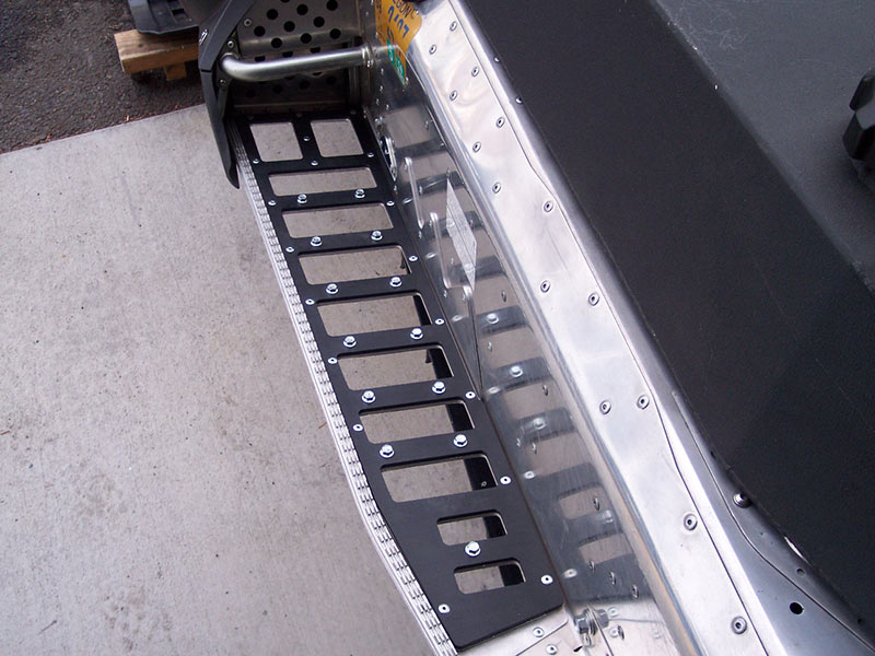
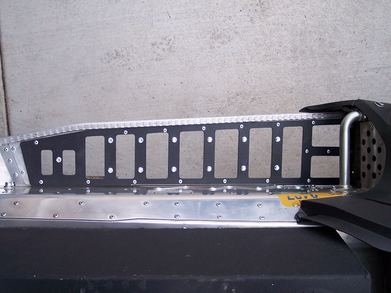
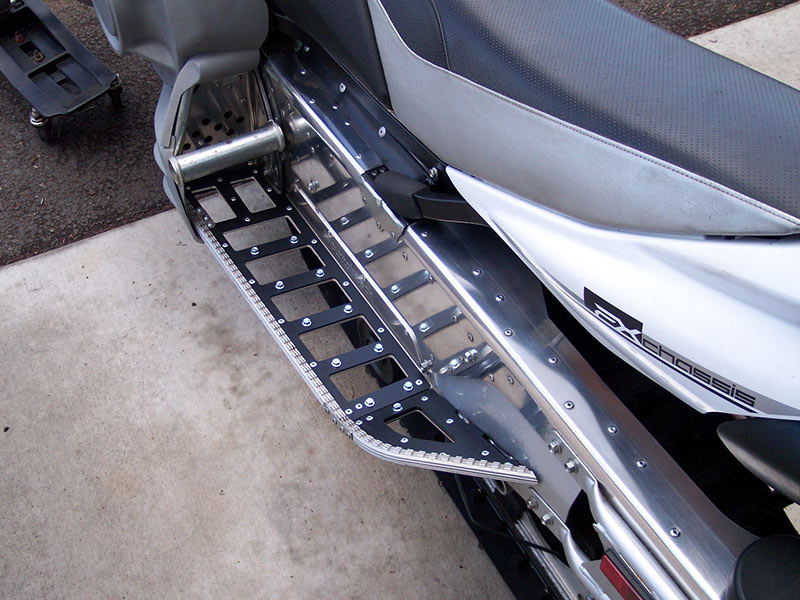
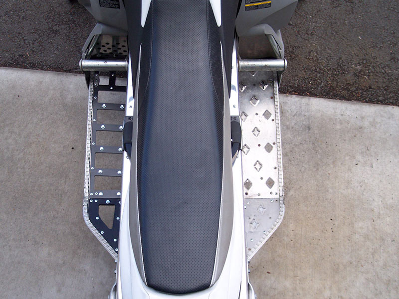
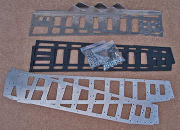
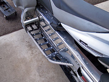
FX Nytro Running Board Kit (Late Version)
The best Running Board Insert Kit available for the FX Nytro with oval footgrip pattern running boards.
Not to be confused with single layer aluminum inserts, Mountaintech has devised a unique 3 layer system, making for the strongest,most snow free, and easiest to install system yet.
The first layer is an aluminum .060" layer that replaces the original running board with one easy cut, and integrates into the factory
edge extrusion. The second layer is a .125" aluminum insert that adds strength. The final top layer is a 3/16" UHMW plastic layer that
provides the non stick component.
All three layers are fastened together with OEM style multigrip rivets and 6mm traction device fasteners.
The traction devices provide more than adequate traction, without destroying footwear.
Most holes are already predrilled in the 3 layers, matching existing chassis holes for easier installation and alignment.
This kit was designed specifically for the 2009+ XTX and 2010+ MTX but will also work on other models with the oval footgrip pattern.
*Price:
$249 - plus
shipping
|
| Mountaintech FX Nytro Running Board (Late) Installation Instructions |
Click to show instructions
DISASSEMBLY
- Remove hood, and upper and lower body side panels.
- Remove all rivets that hold running board outer edge extrusion onto the running board. Holding the back of the rivet with Vise grips will prevent the rivet from spinning while you drill it out with a 3/16" drill bit. Remove outer edge extrusion. Remove any running board bracing plates located on or under the running boards.
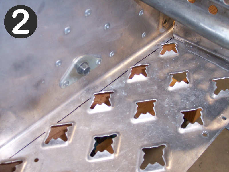
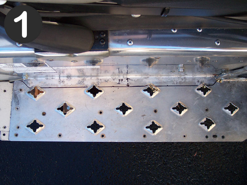
- Mark running board as shown in Pics #1, #2, and #3. You will be drawing a line 13/16" away from the vertical wall of the tunnel the full length of the original running board. You will be cutting along this line. Once the cut is made you will be left with a 3/4" lip protruding from the vertical wall of the tunnel. Measure twice, cut once! A great way of making the cut is to use a jigsaw upside down, cutting from underneath where possible. Once the cut is made, drill out any rivets that are still holding the running board to the chassis. Once you have completed this, you should be able to remove original running board from chassis.
- Smooth and deburr cut edge with a file.
ASSEMBLY
- Lay Mountaintech base plate in place. It is the thin (.060") aluminum plate that replaces the original running board you just cut out. Temporarily fasten (with Clecoes or small machine screws and nuts) the outer edge extrusion to the base plate, the base plate to the footwell bracket, and the base plate to either a rear drop bracket hole , or other bracket hole at the rear. Once everything fits together use the base plate as a template to mark the holes that have to be drilled in the 3/4" lip. Use a 3/16" drill bit to drill the holes.
- Once you're at this point you can place the .125" running board insert on top of the base plate and the UHMW layer on top of the insert. There are some 3/16" holes that need to be drilled through the UHMW layer. This can easily be done from underneath using the lower 2 layers as a template. Once all holes are in place, everything can be assembled with the supplied rivets and traction device fasteners. Three different rivet lengths are supplied.....short, medium, and long. A total of 4 short rivets (2 for each side) are required to fasten the footwell metal bracket to the outer edge extrusion and baseplate. These are inserted from the bottom up. If a longer rivet is used in this position, it will cause the top UHMW layer to bulge. The long rivets are used in all places where a rivet passes through the UHMW layer. The medium rivet is used in all other places. Kits are supplied with more than enough rivets. When installing the traction device fasteners, do not over tighten. Snug is good.
XTX INSTALLATION NOTES
Because this kit also fits the XTX models, there is provision in the insert plate for fastening the suspension rear drop bracket to the base plate. These are the 1/2" holes in the insert plate. When assembling this kit on a XTX, rivets must be placed in these holes and set prior to riveting the UHMW Layer on. Later XTXs also have a tunnel bracket (above suspension drop bracket at bottom of vertical wall on tunnel) that can either be removed, or needs to be notched to accept the Mountaintech kit.
|
|
|
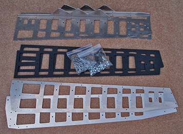
FX Nytro Running Board Kit (Early Version)
The best Running Board Insert Kit available for the FX Nytro with diamond footgrip pattern running boards.
Not to be confused with single layer aluminum inserts, Mountaintech has devised a unique 3 layer system, making for the strongest,
most snow free, install yet.
The first layer is an aluminum .060" layer that replaces the original running board with one easy cut, and integrates into the factory
edge extrusion. The second layer is a .125" aluminum insert that adds strength. The final top layer is a 3/16" UHMW plastic layer that
provides the non stick component.
All three layers are fastened together with OEM style multigrip rivets and 6mm traction device fasteners.
The traction devices provide more than adequate traction, without destroying footwear.
Most holes are already predrilled in the 3 layers, matching existing chassis holes for easier installation and alignment.
This kit was designed specifically for the 2008-2009 MTX but will also work on other models with the diamond footgrip pattern.
This kit also narrows the running boards, similar to the 2010+ MTX.
Trimming of the rear tunnel extension and rear drop bracket required for installation.
*Price:
$249 - plus
shipping
|
| Mountaintech FX Nytro Running Board (Early) Installation Instructions |
Click to show instructions
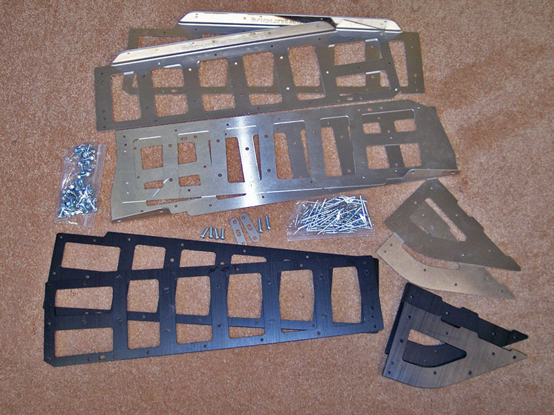
Contents
- 2 Baseplates .063" thick
- 2 Running board inserts .125" thick
- 2 UHMW overlays
- 50 Multigrip rivets long (44 required)
- 30 Multigrip rivets medium (24 required)
- 6 Multigrip rivets short (4 required)
- 26 Traction devices (bolt/nut combo)
- Remove hood, and upper and lower side panels to gain access to lower footwell area.
- Remove all rivets that hold the running board outer edge extrusion onto the running board edge. Holding the back of the rivet with Vise grips will prevent the rivet from spinning while you drill it out with a 3/16" drill bit. Remove outer edge extrusion. It will be reused. Remove any running board bracing plates located on or under the running boards.
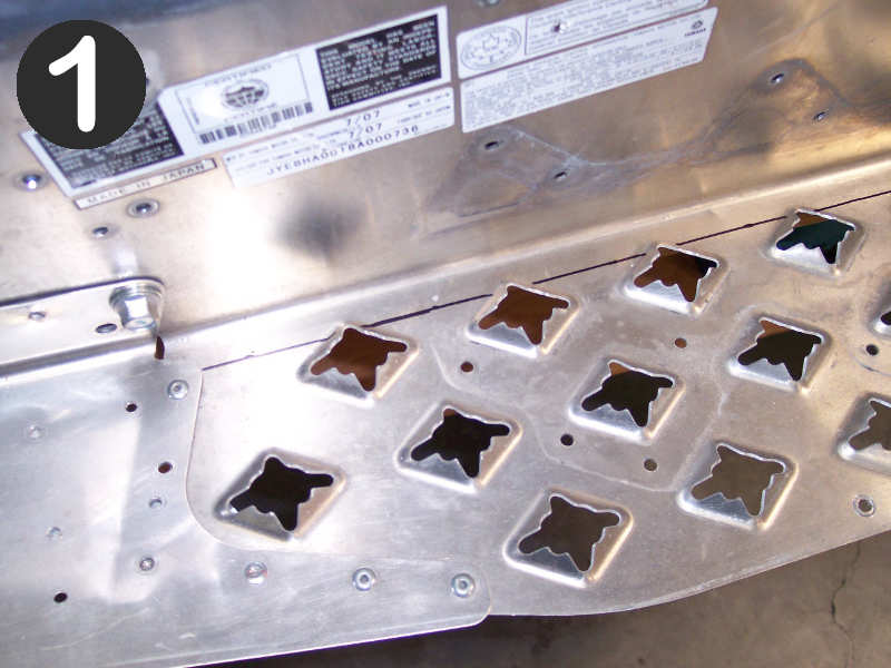
- Drill out the rivets (6 each side) that attach the running boards to the tunnel extension. See Pic #1.
- Drill out the rivets (4 each side) that secure the footwells to the running boards.
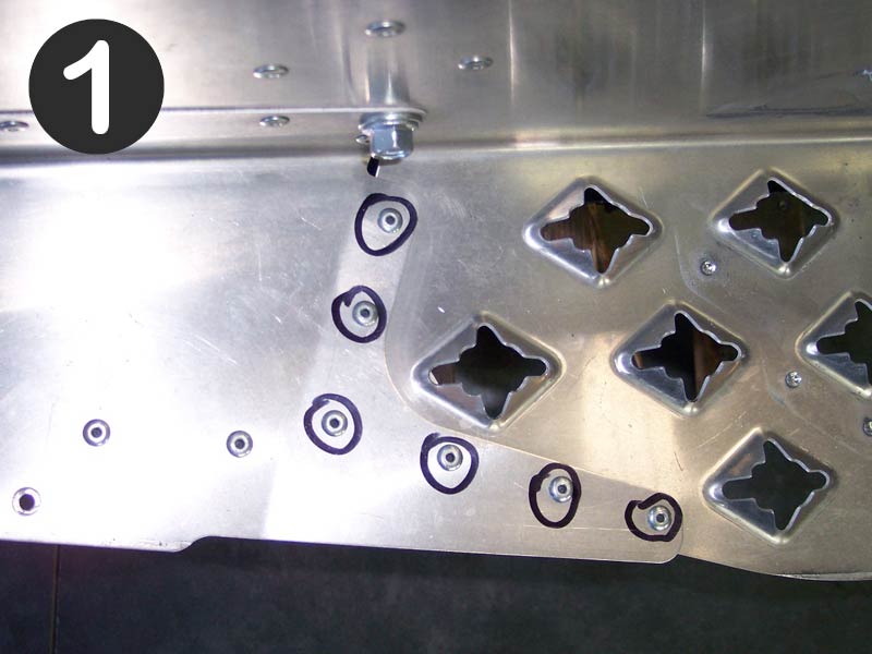
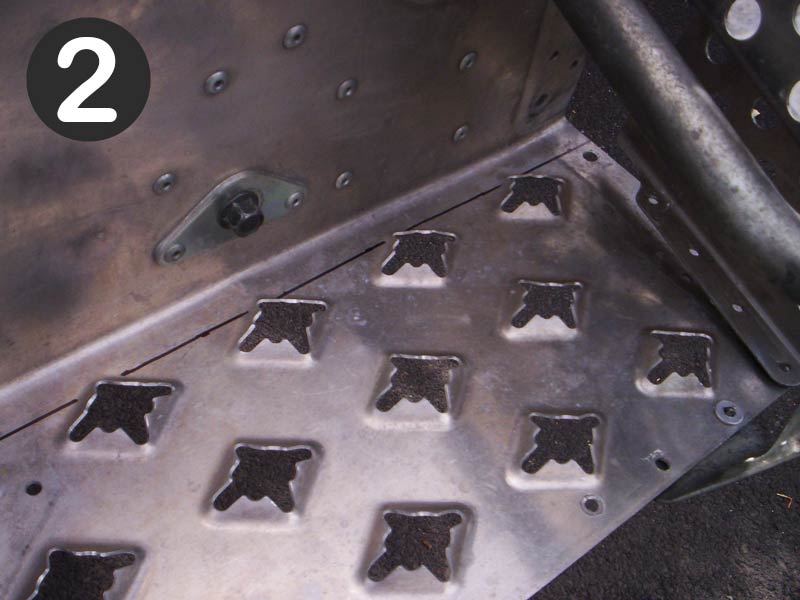
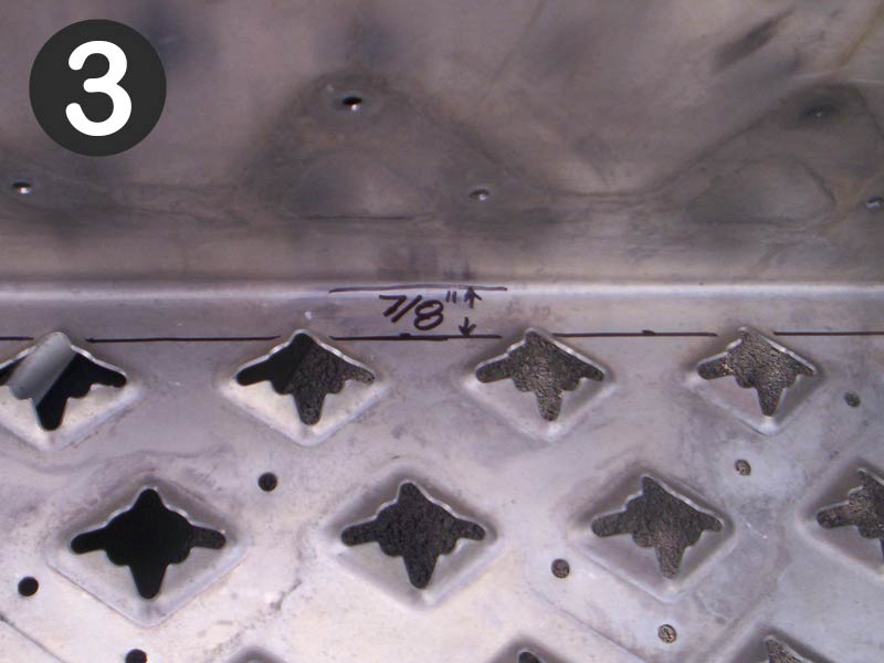
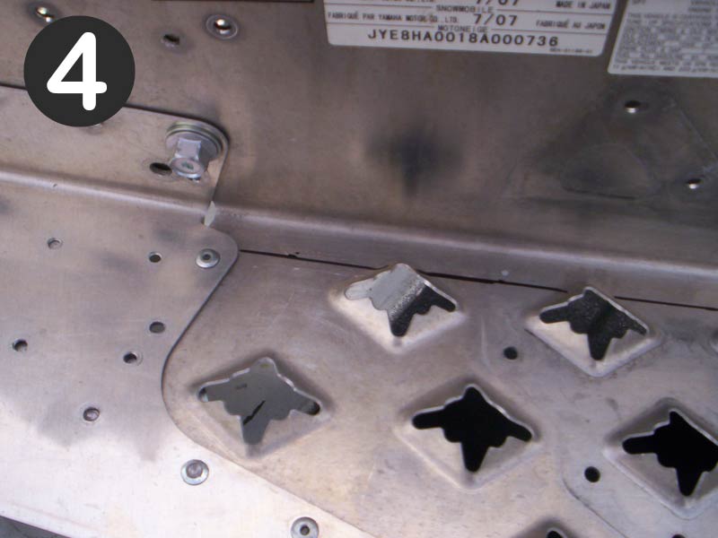
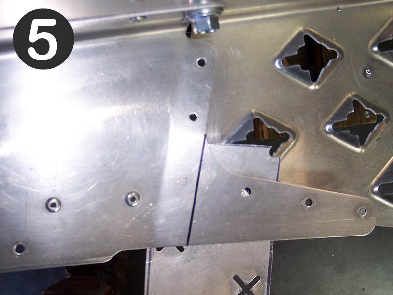
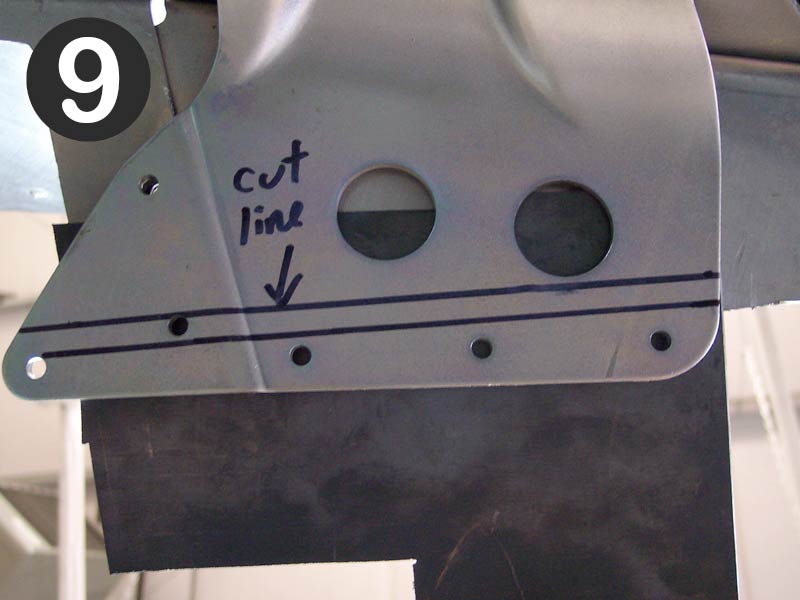
- Mark running boards as shown in Pic #2,3,and 4. You will be drawing a line 7/8" away from the vertical wall of the tunnel, the full length of the running boards. You will be cutting along this line. Once the cut is made you will be left with a 7/8" lip. Measure twice, cut once! A great way to make the cut is to use a jigsaw upside down, cutting from underneath. Once the cut is made, you should be able to remove the original running board from the chassis. The Mountaintech baseplate will replace the original running board upon assembly.
- Smooth and deburr cut edge with a file. Make sure edge is flat. Flatten if needed.
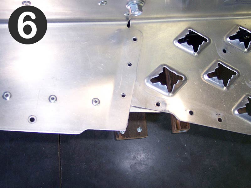
- Mark tunnel extension as shown in Pic #5. Cut along line, taking care not to cut into anything underneath it. Putting a piece of scrap aluminum underneath the area to be cut will protect anything underneath it. Pic #6 shows what tunnel extension looks like after being trimmed.
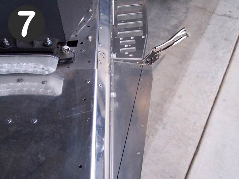
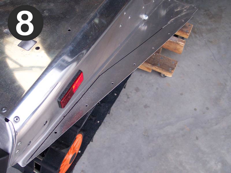
- Lay Mountaintech baseplate in place and draw a line on tunnel extension that follows the rear angle of the baseplate. See Pic #7. Draw another line from the end of the first line to the end of the tunnel. This line should be 1/4" away from the vertical wall of the tunnel. See Pic#8.
- Cut along lines to remove excess material from tunnel extension.
- Once excess material is removed from tunnel extension, you will need to trim the OEM drop bracket brace so it is 5/16" shy of the edge. See Pic #9. Use a scrap piece of metal between drop bracket brace and aluminum tunnel extension to prevent cutting into the aluminum tunnel extension.
- Shorten the OEM outer edge extrusion (previously removed) by cutting a piece off the back so it matches the new and narrower profile of the running boards. Bend the extrusion to match the new profile as well.
- Lay the Mountaintech baseplate in place. Temporarily fasten (with Clecos or small machine screws and nuts) the outer edge extrusion to the baseplate.....the baseplate to the footwell bracket.....and the baseplate to either a rear drop bracket hole, or other bracket hole at the rear. Once everything fits together, use the baseplate as a template to mark holes that have to be drilled in the 7/8" lip. Use a 3/16" drill bit to drill the holes.
- Once you're at this point, you can place the .125" thick running board insert on top of the baseplate and the UHMW overlay on top of the insert. There are some 3/16" holes that have to be drill through the UHMW overlay. This can easily be done from underneath, using the lower 2 layers as a template. Once all holes are in place everything can be assembled with the supplied rivets and traction device fasteners. Three different rivet lengths are supplied.......short, medium, and long. A total of 4 short rivets (2 for each side) are required to fasten the steel footwell bracket to the outer edge extrusion and the baseplate. These are inserted from the bottom up. If a longer rivet is used in this position, it will cause the top UHMW layer to bulge. The long rivets are used in all places where a rivet passes through the UHMW overlay. The medium length rivet is used in all other places. Kits are supplied with more than enough rivets. When installing the traction device fasteners, do not over tighten.
|
|
|
PZ Phazer Running Board Kit
The finest running board kit available for the PZ Phazer. Nothing else on the market comes close!
Not to be confused with single layer aluminum inserts,Mountaintech has devised a unique 3 layer system, making for the strongest, most snow free, and easiest to install system yet. The first layer is a .060" aluminum layer that replaces the original running board with one easy cut, and integrates into the factory edge extrusion. The second layer is a .125" insert that adds strength. The final top layer is a 1/8" UHMW plastic layer that provides the non stick component. All three layers are fastened together with OEM style Multigrip rivets and 6mm traction device fasteners. The traction device fasteners provide great traction, without destroying footwear. Most holes are already predrilled in the three layers, matching existing chassis holes for easier installation and alignment. This kit fits all years and models of the PZ Phazer.
*Price:
$239 - plus
shipping
|
| Mountaintech PZ Phazer Running board Installation Instructions |
Click to show instructions
Contents
2 Forward Baseplates .063" thick (Left and Right)
2 Rear Baseplates .063" thick
2 Running board inserts .125" thick (Left and Right)
2 Forward UHMW Overlays
2 Rear UHMW Overlays
55 Long Multigrip Rivets (50 required)
10 Short Multigrip Rivets (8 required)
22 Traction Devices (Bolt/Nut Combo)
4 Footwell Attachment Fasteners
2 Footwell Attachment Washers
2 Side Panel Attachment Fasteners
- Remove upper and lower forward side panels.
- Remove foot rest assembly. (4 fasteners)
- Remove small L shaped bracket at forward end of running board.
- Drill out all rivets that attach outer edge extrusion to running board. Use a 3/16" drill bit and hold the back of the rivet with a pair of vise grips to prevent the rivet from turning while drilling out. Remove rear portion of OEM running board by drilling out rivets that attach it to the steel drop bracket.
- Drill out all rivets that attach the large L shaped reinforcement bracket to the underside of the running board and vertical tunnel wall.
- Mark the running board as shown in Pic #1. The line drawn should be 1" away from the vertical wall of tunnel. Cut along line. Using a jigsaw upside down and cutting from underneath works well.
- Flatten running board edge. Using 2 pieces of flat metal and vise grips or C clamps works well.
- Use rear baseplate as a template to mark rear portion to be cut out. Using a 3/8" drill bit to put holes at the corners helps before cutting the rest out with a jigsaw.
- Use the forward baseplate as a template to drill out the 4 3/16" holes in the original tunnel edge and the 2 1/4" holes at the rear where the baseplate fastens to the metal drop bracket.
- Use the rear baseplate as a template to drill the 1 1/4" hole in the metal drop bracket.
- Debur and smooth all edges and holes.
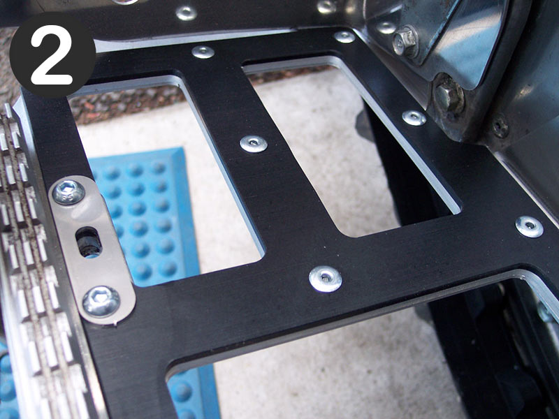
- Assemble using short rivets for the vertical tunnel wall holes and long rivets everywhere else. When installing traction devices, do not over tighten. Snug is good. Reinstall small L shaped bracket at the forward end of running board. Reinstall footwell assembly and use provided hardware (instead of OEM hardware) to attach footwell assembly to Mountaintech running board. See Pic #2
- Reinstall plastic side panels and use provided fasteners to secure side panel to running board.
|
|
|
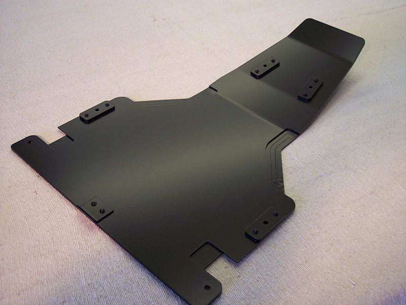
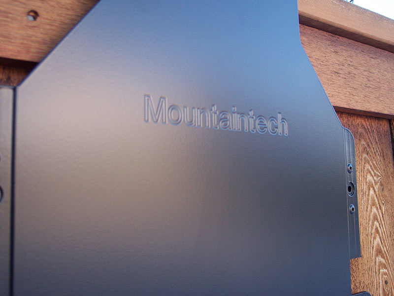
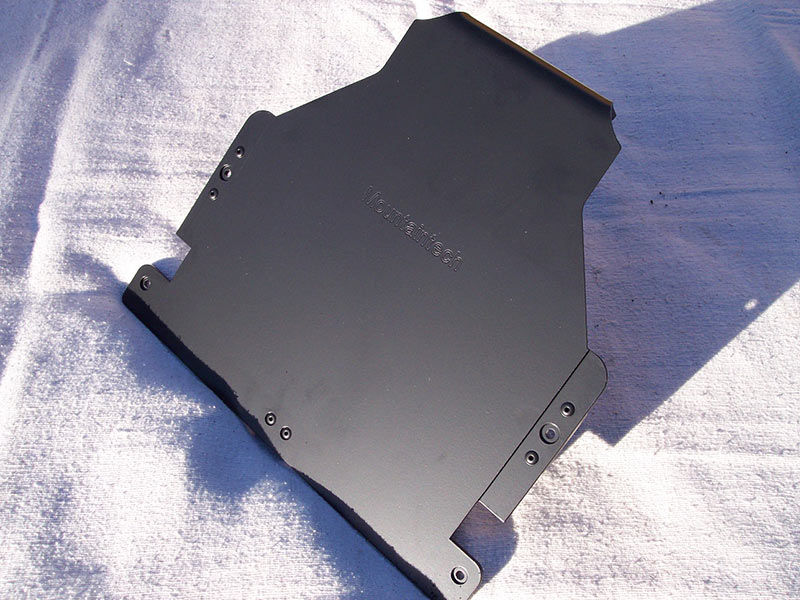
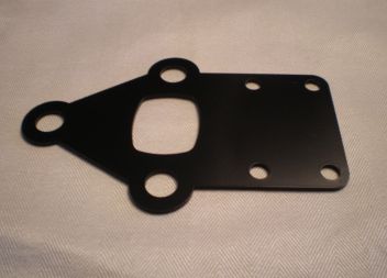
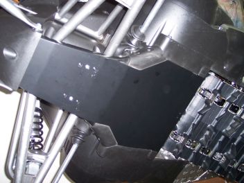
Mountaintech FX Nytro Skid Plate
All the same features of the Shorty Skid Plate but in a full length version. This version extends all the way forward and tucks under the front nose plastic for maximum protection. (NOTE: This skid plate requires purchase of an extra bracket if mounting it on a 2008 model that still has the original subframe. See drop down box below.)
**Click here for installation instructions**
*Price: $169.00 - plus shipping
|
|
|
|
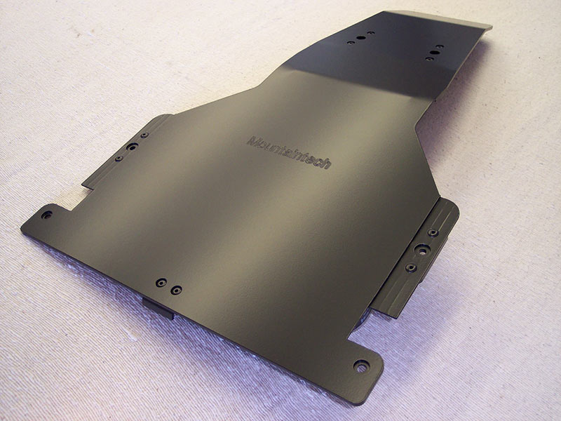
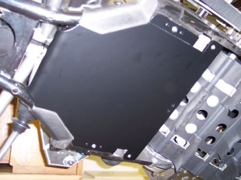
Mountaintech FX Nytro Shorty Skid Plate
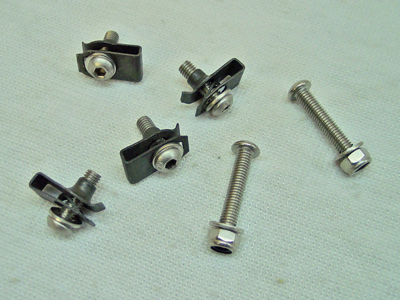
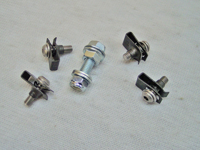
Poor underbody protection is the Achilles Heel of the FX Nytro. The OEM plastic skid plate is not up to the task. Not to mention that it is fastened with plastic push pins. One good hit and you might be very sorry. Protect your engine sump and front heat exchanger with the Mountaintech Shorty Skid plate. Constructed from 3/16" aluminum that is CNC cut, machined, and computer bent, it fits like a glove. It also extends .100" past the lower edge of the front heat exchanger to offer superior protection. Top quality hardware that is easily replaceable is included. All fasteners are recessed or hidden. Easy to install and remove.
**Click here for installation instructions**
*Price: $139.00 - plus shipping
|
|
|